Feedstock purity and chip uniformity on one line
Where the Metal and the Grit Come From on a Wood Chipping Line
Nails, staples, wire and grit ride into the plant on the same branch wood, slabs and used formwork that a drum wood chipper machine is bought to reduce. A drum chipper sets particle size; it does not sort material. This page explains the split that works in practice on a presswood pallet production line, a pellet plant or a biomass fuel preparation system: the chipping stage owns uniform 30 to 35 mm chips, and a dedicated upstream magnetic separation and destoning stage owns purity. EMP supplies both sides as a matched configuration and states the boundary plainly, so the boiler, the mill and the dryer downstream see chips without tramp metal and the chipper sees an even feed.
What the Chipper Owns and What the Separation Stage Owns
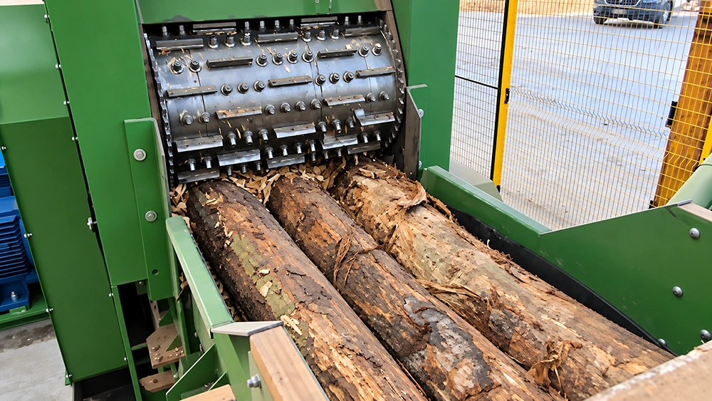
The honest boundary is the one that keeps a project out of trouble. The X-215, X-216 and X-218 drum type wood chipper are chipping machines. Their job is to take irregular wood and produce a repeatable chip length, and the published target is about 35 mm. They do not contain a built-in overband magnet, a metal detector or an air separation chamber, and we will not describe them as if they did. Calling a chipping machine a metal-removal machine is the kind of claim that survives a quotation and fails in commissioning. What EMP does provide is the matched line configuration: magnetic separation for ferrous scrap and a destoning and screening stage for grit, soil and heavy mineral matter, placed upstream of the chipper infeed and ahead of the downstream milling and drying stages as part of the wood powder line scope. That is a two machine answer to a two part problem, and it lets each stage do the job it is designed for. Separation works best on a relatively uniform, spread out material stream, which is exactly what a receiving conveyor and a pre-screen can deliver; chipping works best on clean, evenly presented material, because a hydraulic feeding system with floating upper rollers cannot compensate for a knife meeting a rail spike. The upstream magnetic separation and destoning equipment is quoted, installed and commissioned as its own stage on its own frame, with its own discharge into the chipper feed conveyor or feed chute. If your site already runs a magnetic separator or a destoning screen that you are happy with, the practical route is to interface our chipper with the separation stage you already own, and to agree on the interface point on a drawing before either machine is ordered. Where the contamination route is heavy, such as used formwork or demolition wood, the right first move is an engineering review of the material path rather than an assumption that the chipper will cope.
Matching the Feed Opening to the Material Before Comparing Tonnes per Hour
Selection on a drum chipper starts with what the feed opening and the maximum feed diameter allow, not with the capacity figure, because capacity is only meaningful with the species, moisture content, density, target chip length and steady feeding conditions declared. Three models cover most plant duties and share the same working principle: a heavily welded steel body, a knife roller carrying fly knives held by dedicated bolts and clamping blocks, hydraulic feeding, a chip screen that keeps oversized pieces circulating inside the machine for a second cut, and an adjustable chip length target around 35 mm. The X-215 drum chipper has a 600 mm knife roller, a 400 by 180 mm feed opening and a 160 mm maximum feed diameter, with a 45 kW main motor and a 4 to 5 tph working range. This is a 45 kW wood chipper for plants whose residue arrives as branch wood, edging and small diameter material rather than as large logs. The X-216 drum wood chipper moves to a 650 mm knife roller, a 540 by 240 mm feed opening and a 200 mm maximum feed diameter, with a 55 kW main motor and a 6 to 8 tph working range, which is the middle of the range for a wood chipping machine feeding a presswood or panel line. The X-218 drum chipper is the heavy end, with an 800 mm knife roller, a 680 by 310 mm feed opening, a 300 mm maximum feed diameter, a 110 kW main motor and an 8 to 12 tph working range, and it is the model that suits a wood chipper for presswood pallet line duty where whole logs and thick slabs are part of the recipe. Two structural details matter once contamination is in the picture. First, the feeding arrangement uses upper and lower feed rollers driven in synchronisation by chains and sprockets, with the upper roller floating on the hydraulic system within its range, which holds uneven and mixed thickness material down instead of letting it jump. Second, the same hydraulic system lifts the upper feed roller and opens the cover, so knife changes, knife gap adjustment and inspection of the chipping drum are maintenance tasks rather than a production stoppage, and the drive side is a 380 V electric package with soft start and inverter control of the feeding speed. Full machine weight, overall dimensions, voltage and frequency detail, noise, screen aperture, knife material and hardness, and the test basis behind the capacity numbers are not published yet, so they must be confirmed by engineering before they appear in a layout, a transformer schedule, a shipping calculation or a return on investment model. Do not take these figures from another manufacturer and apply them to Shred.
The Result on the Line: Even Chips In, Clean Chips Out
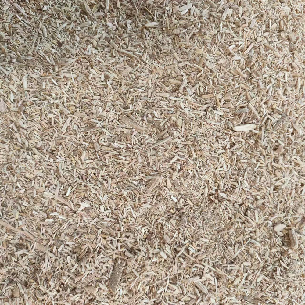
Run the two stages as designed and the line stops arguing with itself. Upstream, ferrous scrap is pulled out and grit, soil and heavy mineral matter drop away, so the material that reaches the knife roller is wood. At the chipper, hydraulic feeding delivers that material steadily, the fly knives cut it to a repeatable length of about 35 mm, the chip screen returns the oversized fraction for another pass, and the discharge conveyor hands a consistent stream to the next stage. Downstream, an even chip length reduces the load on the hammer mill or pulverizer, gives the dryer a more predictable inlet, supports the binder and pressing window on a presswood pallet production line or a panel line, and gives a boiler or a pellet mill a fuel or furnish whose ash forming mineral content is controlled at the point where it can be controlled, instead of at the grate or the die. The plant also gains a maintenance picture it can plan: fewer knife and screen incidents from unexpected metal, fewer unplanned stops, and a knife change routine that is scheduled rather than reactive. To size this honestly, send us the material mix you actually receive, including how much of it is used formwork or demolition timber, the maximum diameter and typical length of the pieces, the moisture content and species mix, the target tonnes per hour and the shift pattern, whether you already run separation equipment and where it sits, and the available floor space, foundation and power supply. With that, we can propose a feed opening, a main motor and a working range, and mark clearly which parts of the package are Shred chipping scope and which are the upstream separation scope, so the quotation reads the way the plant will actually be built.
- Feedstock state and downstream consequences are described before any equipment is named, and no separation capability is attributed to the chipper body.
- Every published figure used here comes from EMP Shred product data: 160, 200 and 300 mm maximum feed diameter, 45, 55 and 110 kW main motors, 4 to 5, 6 to 8 and 8 to 12 tph working ranges, and a chip length of about 35 mm.
- The upstream magnetic separation and destoning stage is presented as a separate machine on a separate frame, with an interface point agreed on a drawing before order.
- Undisclosed data such as weight, overall dimensions, noise, screen aperture, knife material and the capacity test basis is flagged as engineering confirmation required and is not borrowed from another manufacturer.